
As we worked with the computer shown in Figure 2.1., we need a series of stages and certain methods in order to be able to produce aim for our objectives. Likewise in the software engineering, it needs certain stages to be productive. A successful software engineering needs not only strong computation capacity like algorithm, programming, and database but also strong, but also determination in meeting the goal, resolution method identification, development method, goal identification, resources requirement identification, and other factors. Such matters are related to software engineering methods.
The content of this chapter not within the standard Software Engineering competence. However, the writer think it would be beneficial to know how to carry out software engineering and methods that normally being used. Several part of this chapter will likely difficult to understand, teacher may be needed to explain. The summary of the chapter is written at the end of the chapter. (Source: Microsoft Office 2007 Clip Art)
OBJECTIVES
After you learn this chapter, you should be able:
- Understand the general characteristics of the process model in software engineering.
- Name several models of the software engineering.
- Know principles from the method waterfall, prototyping, and unified process
- Understood the stages in the software engineering.
2.1 SOFTWARE ENGINEERING PROCESS MODELS
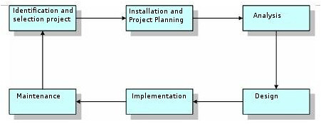
There are many models were developed in Software Engineering to help the process of software development these models generally refer to the system development process model that was known as System Development Life Cycle (SDLC) as shown in Figure 2.2. Figure 2.2. System Development Life Cycle (SDLC). Each developed model has its own characteristics. However, in general, these models will fall into the following categories, namely:
- Need for clear definition of the problem. Main input in each software development model is in clear definition of the problem. The clearer the definition the better for problem solving processes. Thus, understanding the problem as explained in Chapter 1, is an important part of a software development model.
- A structured development stages. Although software development models may have different pattern, usually these models followed a general pattern of analysis . design . coding . testing - maintenance.
- Stakeholder plays a very important role in the whole of the development stage. Stakeholder in the software engineering may be the user, the owner, the developer, programmer and people who are involved in the software engineering.
- Documentation is an important part of software development. Each the stage in the model usually produces several articles, the diagram, the picture or other forms that must be documented and must not separated from the produced software.
- The output of software development processes must have an economic value. Although the value of software may be difficult to measure in terms of money. The effect of software usage give an added value to the organization. This could be in form of declining operating cost, efficient use of resources, increase in profit, improving organization image, etc.
There were many software development models, including The Waterfall Model, Joint Application Development (JAD), Information Engineering (IE), Rapid Application Development (the COUNCIL) including Prototyping, Unified Process (UP), Structural Analysis and Design (SAD) and Framework for the Application of System thinking (FAST). This book will discuss three (3) development models, namely, The Waterfall Model, Prototyping, and Unified Process (UP).
2.1.1.The Waterfall model
The life-cycle model is the main model and the foundation of many models. One of the models that is globally known in software engineering is The Waterfall Model. There are five (5) main stages in The Waterfall Model as shown in Figure 2.3. Known as waterfall since the process stage diagram resembled the stratified waterfall. The brief stages in The Waterfall Model are as follows:
- Investigation stage is to determine whether a problem happening or is there an opportunity to develop an information system. In this stage the feasibility study must be carried out to determine whether the developed information system would be an appropriate solution.
- Analysis stage aim to look at the user and organization requirement as well as analyzing the available condition before the application of the new information system.
-
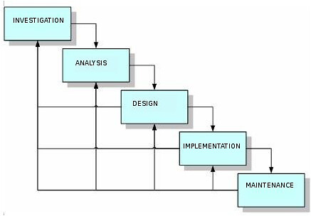
Design stage determine the detail specification
of the information system components, such as, human, hardware, software, network and data, and information products that in accordance with
results of the analysis stage. - Implementation stage is to get or to develop hardware and software (program coding), carried out testing, training and migration to the new system.
- Maintenance stage carries out during the operation of the information system. In this stage, monitoring process, evaluation and improvement when being needed are carried out.
2.1.2 Prototyping model
Prototyping is one of software engineering approach that directly demonstrated how a software or software components will work in its environment before the actual construction stage is carried out (Howard, 1997). Prototyping model could be classified to several types as shown Figure 2.4.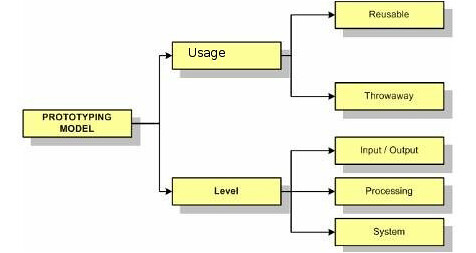
- Reusable prototype: Prototype that will be transformed to the final product.
- Throwaway prototype: Prototype that will be thrown away as it completes its job.
- Input/output prototype: Prototype that was limited to the user interface.
- Processing prototype: Prototype that covered the maintenance file the foundation and processes of the transaction.
- System prototype: Prototype that took the form of the complete model from software.
The stages in prototyping is normally an accelerate stages. The main strategy in prototyping is to build the easiest first and deliver to the user as soon as possible. Harris (2003) divided prototyping in six stages as being seen in the Figure 2.5.
The stages could be briefly explained as follows: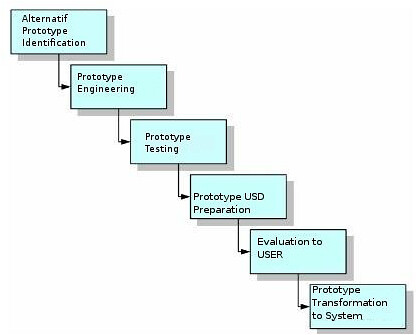
- Identification of the candidate prototyping. The candidate in this case covers user interface (menu, dialogue, input and output), main transaction file, and functions of basic processing.
- Engineering of prototype with help software like word processor, spreadsheet, database, graphics processor, and CASE (Computer-Aided System Engineering) software.
- Test prototype to confirm prototype able to undertake demonstration purposes.
- Prepare prototype USD (Userfs System Diagram) to identify parts of software that would be prototyped.
- Evaluate prototype with the user and carried out changes if being needed.
- Transform prototype into fully operated software and remove unnecessary codes, add needed programs, repeatedly improvement and test the software.
2.1.3 Unified Process and Unified Modeling Language
Unified Process (UP) or sometimes known as Unified Software Development Process (USDP) is the framework of development processes that use-case-driven, focus on software architecture, iterative and easy to grow (Alhir, 2005).
This framework is a relatively new in software development methodology. UP could be applied in various project scale, from small up to large scale. Short description of the four (4) stages in UP are as follows:
- Inception. This is the earliest stage that assess the carried out software project. It aims to get an agreement from stakeholders on its goal and project funding.
- Inception. This is the earliest stage that assess the carried out software project. It aims to get an agreement among the stakeholders on the objectives and project funding.
- Elaboration. The stage's objective is to get the picture on the general requirement, the condition and its main functions. This is important to know project risks, including software architecture risk, planning risk, and implementation risk. Despite its early stage, software engineering activities including business modeling, requirements, analysis and design are performed through iterative processes.
- Construction. This stage's objective is to construct the software to be used. The focus of this stage is to determine the level of priority in its requirement, its specification, in-depth analysis, the solution design to meet the requirement and the condition, coding and testing of the software. If possible, do beta testing to get early input from the user.
- Transition. The focus of this stage is to deliver the software to end user. Software would officially tested by both competent beta tester as well as the end users. Several activities, such as, data center migration, end user and staff training, should be performed in this stage.
In software development based on UP, UML (Unified Modeling Language) is normally used. Although UP requires the use of UML, ULM can be use in various methods including other field out side information system field. UML is a standard modeling language and a collection of modeling techniques to specify, to visualized, to construct as well as to document the work during software development (Fowler, 2004). UML was born from in merging of many object oriented graphics based modeling languages developed in the end of the 80's and early 90's.
UML is simply used to draw the sketch of the system. The developer used UML to send several software aspects through graphic notation. UML defined notation and the semantics. Notation is a collection special forms that has certain meaning to depict various diagrams of software and the semantics defined how these forms could be combined. There are several kind of diagrams that are provided in UML, including:
- Use-case diagram. This diagram is used to show the use-software interaction.
- Activity diagram. This diagram is used to show the behavior of the software.
- Class diagram. This diagram is used to show class, feature, and relations. his diagram, object oriented approach plays an important role.
- Sequence diagram. This diagram is used to show the interaction among objects with the emphasis on process sequence or events.
- State machine diagram. This diagram is used to draw how an event change an object in its lifetime.
- Component diagram. This diagram is used to show the structure and the component connection.
2.2. STAGES IN SOFTWARE ENGINEERING
As described, despite different approaches, models have some similarities in using the following pattern, namely, stage analysis-design-coding(construction)-testing-maintenance.
2.2.1. Analysis
System analysis is a problem solving technique that break a system into smaller components to examine or to evaluate the component performance and its interaction to reach its objectives.
The analysis may be a crucial part of software engineering processes. The next processes will be highly depend on the analysis results. The brief stages in software engineering analysis is shown in Figure 2,7. 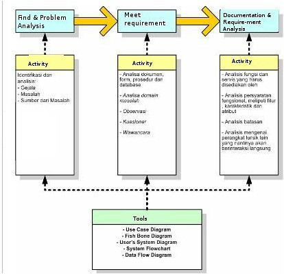
One of the most important part that usually carried out in the analysis stage is the business process modeling. Process modeling is a model that focused in all processes in the system that transform data to information (Harris, 2003). Process modeling shows data flow that enter and exiting in a process. This model is usually depicted the Data of Flow Diagram (DFD). DFD describe man, process and procedure interaction in transforming data into information.
2.2.2. Design
Software design is the task, the stage or the activity that focused on the detail specification of a computer based solution (Whitten et.al, 2004).
Software design often refers as physical design. While system analysis stage stress on business aspect, software design focuses on technical and implementation side of a software (Whitten et.al., 2004).
The main output from software design stage is the design specification. The specification covers the general design specification for the system's stakeholders and detailed specification to be used in the implementation stage. The general design specification contains the general picture of the software for the stakeholders. USD diagram on the software is normally the important point in this stage. The detail design specification or the detail architectural software design is needed to do system design so as to have a good construction, an exact and accurate data processing, valuable, user-friendly and has a good foundation for further development.
The architectural design consists of the database design, the process design, the user interface design including input design, output and report form, hardware design, software and the network. The process design is the continuation of process modeling that carried out in the analysis stage.
2.2.3. Construction
The construction is the stage that translate the logical and physical design into computer program codes. Construction techniques and methods will be described in more the detail in this book.
2.2.4. Testing
System testing involves all planned user groups. The level of acceptance is evaluated by all user groups based on the determined criteria.
2.2.5. Maintenance and Configuration
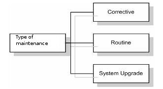 When a software is considered appropriate to be used, the next stage would be the software maintenance. There were several software maintenance types known as shown in Figure 2.12.
Corrective maintenance is carried out to circumvent errors known as bugs. The maintenance Is carried out by improving the code, increased the some parts or eliminated certain parts.
Routine maintenance is also known as preventive maintenance is carried out routinely to maintain the performance of the software whether there is any mistakes / errors or not.
System upgrade maintenance is carried out to change any components of the software. For example, platform or operating system changed, old to new version change require upgrade of the software.